Grain Elevator Design: 6 Questions to Address Before Selecting Equipment
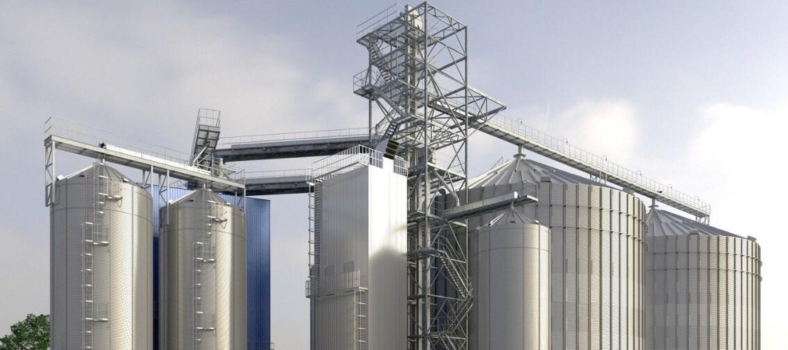
When designing a new grain elevator or reconstructing an existing facility, the first thing to consider is capacity: how many tonnes per hour the facility needs to receive, convey, or dispatch.
However, this alone is not enough to develop a process flow diagram. Grain flow routes, simultaneous operations, crop characteristics, the operation of process units, and the need for redundancy must also be taken into account. This is the logic behind process flow design: from initial data and grain routes to capacity calculations and equipment selection.
Question: What are the benefits of a properly designed process flow diagram?
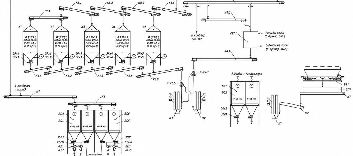
It makes it possible to determine, even before purchasing and installing the equipment:
— which routes the grain will follow;
— which operations can be performed simultaneously;
— where buffer storage bins are required;
— what equipment capacity is required at different sections;
— where redundancy is necessary;
— which crop characteristics must be taken into account.
These decisions ultimately determine the structure of the process flow diagram and the equipment configuration.
Where Does Grain Elevator Design Begin?
It starts with the initial data.
It is necessary to determine the receiving and dispatch volumes, the types of crops, the operating time of the lines, the need for drying and cleaning, and the number of batches that are planned to be received, stored, or dispatched simultaneously.
Next, the main process units and the connections between them are defined: receiving, cleaning, drying, storage, and dispatch. Grain flow routes are developed, and it is determined which of them must operate simultaneously. Based on this, calculations are performed to determine the required quantity and capacity of conveying and process equipment.
Therefore, equipment selection is the next stage after defining the operating logic of the facility.
Grain Flow Routing
After defining the required process units and taking into account the conditions of the future facility site (including the customer’s vision of what should be located where), the units are schematically placed on paper as blocks. Arrows are then used to show the connections between them, forming a basic diagram of the grain flow routes within the future facility. For the expansion or reconstruction of existing facilities, the approach is similar, but the diagram must take into account the location and purpose of existing structures.
If a capacity of 200 t/h is required, can all equipment be selected for 200 t/h?
At first glance, the logic seems simple: if the facility requires a capacity of 200 t/h, all conveying lines and process units can be designed for the same 200 t/h. In practice, this approach often leads either to bottlenecks or, conversely, to an unjustified increase in equipment capacity.
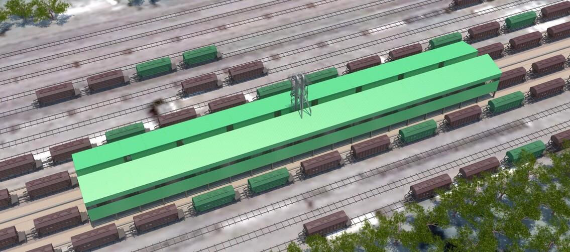
The reason is that rated capacity does not account for all actual operating conditions. For example, when receiving wet and contaminated grain directly from the field, the actual capacity of conveying equipment may be 30–40% lower than when handling dry, cleaned grain. Flowability, bulk density, and resistance to product movement change, meaning that the same machine effectively operates under different conditions.
An even more illustrative example is the drying section. When drying corn with an initial moisture content of 28–30%, the capacity of the grain dryer may decrease by 2–2.5 times. Ambient temperature and humidity also affect its performance. Therefore, when designing the process flow, it is important to consider not only the rated capacity of the dryer but also its actual throughput under specific operating conditions. Buffer storage bins may be required to synchronize the flows, while the conveying equipment in the drying section should have an appropriate, technologically justified capacity margin.
However, this margin should not turn into overdesign. Otherwise, the customer ends up with more expensive equipment, higher installed power, additional load on the electrical grid, and increased operating costs.
Therefore, grain elevator capacity cannot be designed according to the principle of “one capacity figure for all equipment.” The entire product route must be calculated — from receiving and cleaning to drying, storage, and dispatch — taking into account the actual characteristics of the grain and the throughput of each process unit.
Why Are Buffer Bins Needed in the Process Flow?
They help coordinate equipment operating at different capacities or in different operating modes.
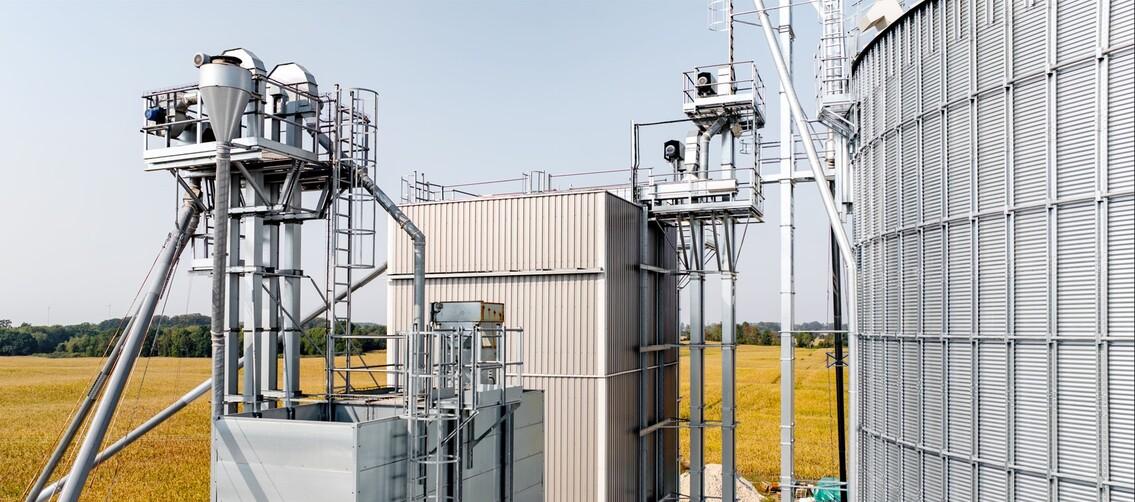
In the drying section, a buffer of wet grain ensures stable loading of the dryer. The capacity of wet grain hoppers is recommended to provide 8–24 hours of continuous dryer operation. Post-dryer bins can accumulate dry grain while the conveying line is being used for other operations.
Another example is truck loading.
While one truck leaves the loading point and the next takes its place, it is preferable to keep the conveying flow running. Therefore, the capacity of buffer bins is calculated based on the capacity of the design truck plus sufficient reserve for at least 30 minutes of continuous operation of the conveying equipment.
In this way, buffer storage allows the line capacity to be used more efficiently.
Is It Better to Install the Separator Before or After the Dryer?
There is no universal solution.
Before drying, it is advisable to remove coarse impurities from the grain. After drying, primary cleaning may be required to remove light and fine impurities or broken grain. Therefore, the process flow may include different routes depending on the condition of the raw material and the required cleaning result.
There is also an economic factor. Cleaning efficiency may be higher after drying, but impurities that could have been removed earlier will also consume energy during the drying process.
As grain elevator designers put it simply: “drying waste costs money.”
Therefore, the location of the separator depends on its function within a specific process flow: preliminary cleaning, primary cleaning, or grain preparation before dispatch.
Why Is It Important to Know in Advance Which Crops the Facility Will Handle?
The technological properties of different crops affect drying, cleaning, permissible conveying speeds, the angles of gravity-flow equipment, equipment tightness, and grain damage.
For sunflower, for example, a steeper angle of gravity chutes must be taken into account. For rapeseed, tightness of joints is particularly important. Peas, beans, soybeans, and lentils require gentler handling. For corn, particular attention is paid to drying and minimizing grain damage.
Simultaneous operation is also important. If the facility plans to receive two crops simultaneously without mixing them, the process flow must provide two independent routes even if one would be sufficient in terms of overall capacity.
Is It Necessary to Duplicate Conveying Routes?
This depends on the requirements of the specific facility.
A backup route allows operations to continue if one of the conveying elements is stopped or under maintenance. At the same time, route duplication increases the number of conveyors, valves, and other equipment and makes the process flow more complex.
Therefore, the need for redundancy is discussed before the design process begins and specified in the technical requirements.
A similar balance is required when using gravity-flow systems. They use gravity to move grain, but excessive bucket elevator heights and long gravity-flow sections can make subsequent maintenance more difficult.
Therefore, every additional piece of equipment or route in the process flow must serve a specific technological purpose.
Summary
The efficiency of a process flow depends on the coordinated operation of all its units.
Receiving, conveying, cleaning, drying, storage, and dispatch must operate as a single system, taking into account the facility’s actual operating conditions.
That is why effective design begins with an analysis of the process technology, while the selection of specific equipment becomes the result of this analysis.