Grain Elevator Process Flow: What to Consider Beyond Grain Movement
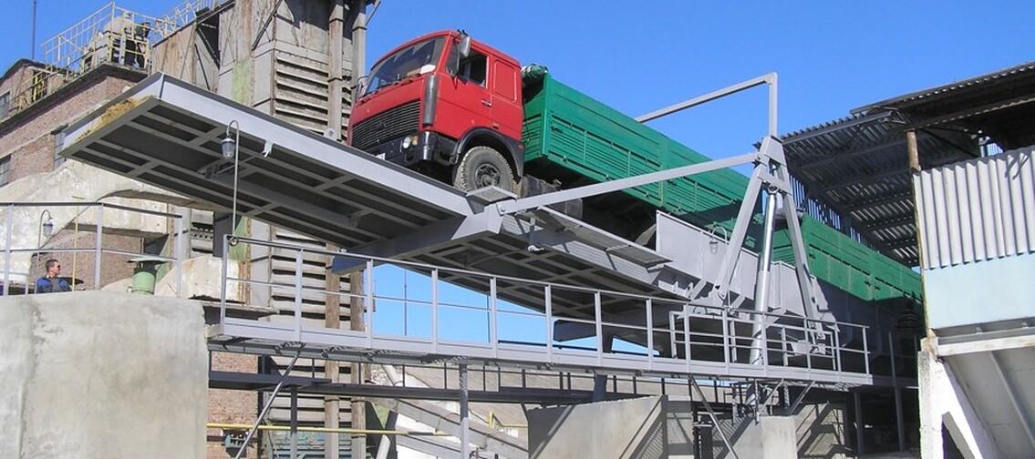
In a grain elevator process flow diagram, the main grain flow is easy to follow: grain is received, cleaned, dried if necessary, and then directed to storage or loading.
At the same time, other process flows are formed within the facility. By-products and waste are discharged from separators. Dust is generated at transfer points. Grain weight and quality must be monitored at different stages. Aeration systems operate in the silos, while the equipment is integrated into automated process routes.
All these processes must be coordinated with the main grain flow already at the design stage.
By-product and waste removal
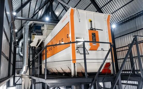
After cleaning, several product streams are generated.
The main grain stream is directed to storage or loading.
The by-product stream, which still contains a portion of grain products, is collected separately and can subsequently be used, in particular, for animal feed production.
Unusable waste — soil, stones, large pieces of straw, dust, and other impurities — is directed to separate containers for subsequent disposal.
Therefore, when designing the grain cleaning section, it is important to determine from the outset how many streams leave it, where they are directed, and what hopper capacities are required.
Grain Weight Measurement at Different Processing Stages
Weight measurement depends on the specific operation.
Truck scales, rail scales, and hopper scales are used for external weighing. For internal flow monitoring, continuous weighing feeders and belt scales can be used.
Grain Quality Control and Sampling Points
Along with quantitative measurement, grain quality control points are also defined.
In addition to laboratory testing, the process flow diagram may include sampling devices:
- from truck bodies;
- from railcars;
- from gravity-flow grain streams.
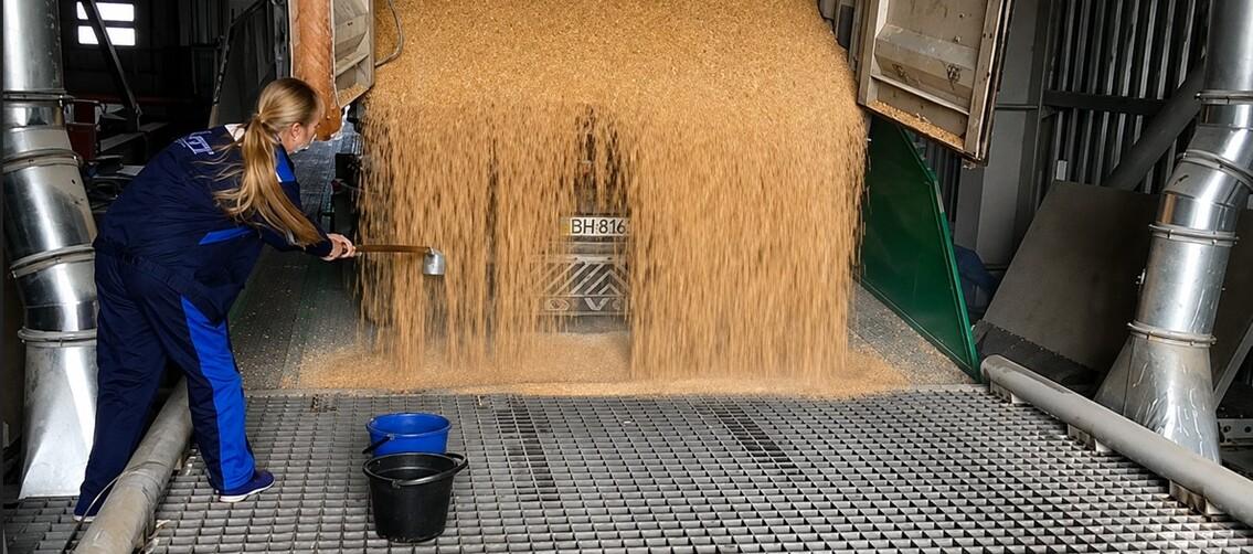
Their type and installation location are agreed with the customer during the development of the process flow diagram.
Thus, quality control is carried out at specific points in the technological process.
Active Grain Aeration in Silos and Hoppers
Active grain aeration systems must be designed exclusively by the silo or hopper manufacturer. The storage structure must be designed to withstand the pressure of both the grain and the airflow generated during active aeration.
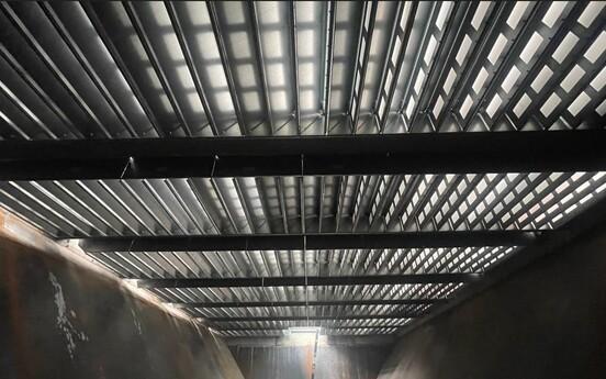
The system typically consists of perforated floor ducts, high-pressure supply fans and, in some cases, roof fans for removing displaced humid air.
Roof fans can also be used to ventilate the headspace above the grain in order to prevent moisture condensation on the silo structures and, consequently, the wetting of the upper grain layer.
Active aeration systems are used to prevent grain self-heating and to reduce the temperature of the entire grain mass.
In hoppers containing wet grain, intensive aeration is used for temporary stabilization and cooling before the grain is fed to the dryer.
For flat-bottom silos, the purpose is different — maintaining the grain mass during storage. Therefore, the system parameters are determined based on the selected silos and their operating conditions.
Main Dust Aspiration Points at a Grain Elevator
Dust is generated wherever grain is conveyed, falls, or changes its direction of movement.
The main dust aspiration points include:
- grain receiving units;
- transfer points between conveyors and bucket elevators;
- grain loading points at hoppers and silos;
- discharge points from storage bins;
- grain loading and dispatch units;
- grain cleaning equipment.
Dust-laden air from these points is directed to dust collection equipment.
Therefore, the dust aspiration system must be coordinated with the layout of conveying and process equipment during the design stage.
Dust Removal and Disposal After Aspiration
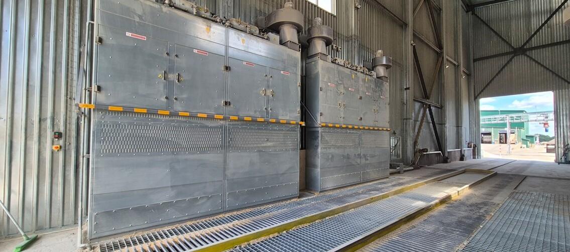
After being separated from the air, the collected dust becomes a separate process stream.
In centralized systems, the collected dust is discharged through sealed rotary airlocks into a waste hopper. Separate conveyors can be used to transport the collected dust.
Dust collected by a centralized aspiration system must not be mixed with marketable grain or by-products.
Therefore, aspiration system design involves two separate routes: the flow of dust-laden air and the subsequent movement of the collected material.
Automation of Grain Elevator Process Routes
The control logic is developed together with the process routes.
For each grain flow, it is necessary to determine which conveyors, bucket elevators, gates, and valves are involved. Some routes can operate simultaneously, while others may be mutually incompatible.
The automation system operates according to this process logic and allows the operator to control routes, gates, and valves from a single workstation.
Therefore, automation solutions should be developed together with the process logic of the facility.
Development of the Grain Elevator Process Flow Diagram
After the basic process routes have been developed, calculations are performed to determine the required number and capacity of equipment, taking into account its approximate layout, elevation differences, and the possibility of using gravity-flow equipment.
The process flow diagram is then prepared graphically.
It shows the interconnections between equipment and storage bins, as well as the flows of grain, waste, and aspiration air.
In this way, individual machines are integrated into a complete process system for the facility.
Conclusion
The process flow diagram should visualize the movement of the product:
grain → waste → weighing and accounting → quality control → aeration → dust aspiration → automated control.
Coordinating these systems at the design stage makes it possible to create an integrated process system in which each process is interconnected with the others.